Light-Up Paper Circuits Mural at Maker Faire!

https://www.instagram.com/p/BxoWKy8hg-5/?utm_source=ig_web_copy_link

This year at Maker Faire, the Nueva I-Lab team and I pulled out my favorite trusty, easy-to-prep maker activity to offer at our school’s booth. We joked that essentially, we were asking visitors who stopped by our booth to build our sign for us as the Faire went on. 🙂

Many parents and teachers who came by asked about how to do this activity back home, so here’s my very quick set of notes:

Prep

Prepping for this activity took maybe an hour or so. First, you have to plan out what design you want to use as your mural backing – I kept it simple with spelling out our school’s name.

Then you have to plan out how you will lay down parallel positive and negative tracks that follow this design. For letters like U, V, and N, this was pretty easy. For letters like E and A, you have to plan strategically and be prepared to use non-conductive tape like Scotch tape, masking tape, or electrical tape (which is actually not conductive despite its confusing name) to insulate junctions to prevent short circuits. If that last sentence made zero sense, choose an easy design like U, V, N, (or C, D, I, J, L, M, O, S, W, Z) for your first go. You can sort of see how I laid out my letters in this photo:

https://www.instagram.com/p/Bxk8cT8hysU/?utm_source=ig_web_copy_link

Once you have planned it out, sketch out your plan on your mural backing surface in pencil, so you have something to follow as you are laying down the copper tape.

Then you will apply the copper tape to create the two parallel tracks. I usually use a thicker piece of tape for the positive track and a thinner piece of tape for the negative track – this is only for aesthetic (and remembering) purposes because the tape will conduct electricity just fine however wide it is. Try not to break the tape to round corners and instead use a folding technique. (The always-wonderful Jie Qi has some great tips about how to round corners without tearing the copper tape.) If you have to connect two separate pieces of copper tape, I usually assume the adhesive side is not conductive and do a fold-under, followed by another piece of tape on top to secure, to make sure the shiny sides are in contact. (Again, Jie Qi has great tips for this too.)

Once you have finished creating the design, figure out where you want to place the battery pack. Place the red wire in contact with the thicker copper tape track on the mural backing and place the black wire in contact with the thinner one. You may need to strip the two wires from the battery pack to expose more wire. Secure with tape and/or thumbtacks. If you want to get fancy, you can even solder these wires onto the copper tape surface. Anything to make a strong electrical connection. You will also need a way to mount the battery pack – Velcro works well but so does a loop of duct tape or even a giant clip of some sort.

Grab a plain LED and test out your mural backing to make sure it’s getting power (remembering that LEDs have a positive and negative leg, so if it doesn’t light up right away, flip it around and test again), and then you are good to go

Supplies

Here’s the list of stuff I usually buy for this activity – for something like Maker Faire which is about 2.5 days of a constant stream of visitors, I think we went through about 200-300 LEDs (a small number of the packs will be defective).

  • Fast cycling LEDs – these wonderful LEDs are already built to cycle through different colors without extra logic or coding. Sparkfun and Adafruit sell these but lately, I have preferred to order them from Amazon in bags of 100. I recommend the fast cycling versus the slow cycling because they are much more “blinky!”
  • Two-AA battery packs and AA batteries: The LEDs above run on about 3V, so you will need battery packs that hold two AA batteries. Get the packs with on/off switches so it’s easy for you to cut power to the whole mural at once.
  • Copper tape: The width of the copper tape has no bearing on its function. But I generally prefer to buy a roll or two of the 1-inch wide copper tape for creating the mural backing. I also buy many more rolls of the more normal 1/4-inch wide copper tape, which is what kids will use to create their pieces before adding to the mural. Pro tip I learned from a 6th grade colleague at my previous school: To avoid a messy tangle of tape falling off the roll literally 5 seconds after the activity starts, pre-cut short strips of tape so kids just grab from these for their project.
  • Paper surface: If you are doing this at your school, you can easily just layer some butcher paper or poster paper on top of an existing bulletin board and then create your mural backing directly on it. I am personally a fan of this black railroad board (blinky lights stand out well against a dark background) but really any surface will do.
  • Thumb tacks: While I hate old-school thumb tacks as much as the next person because they are so hard to pry off, they work really well for this project because they are usually also conductive and so can help with making an electrical connection between the mural backing and the mural pieces on top.
  • (Optional) Cork/foam boards: Because we were doing this at Maker Faire, we needed a portable version of a bulletin-board-like surface. I used to use plain foam core but found that thumb tacks don’t stay in very well. After many iterations of this project, the best solution I’ve found so far is these cork-lined foam core boards. For some reason, they have gotten more and more expensive, so again, if you have a bulletin board to do this at your school, then please skip this step. Otherwise, it’s $$$ but at least you can reuse these for years to come.
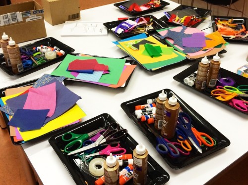
  • Craft supplies: I prefer to keep things simple in this category and just limit it to fun papers, markers, scissors, Scotch tape, and glue sticks (not hot glues since that would be a nightmare to supervise at an event like Maker Faire). For paper, I love love love to buy packs of scrapbook paper – Colorbok is a major brand and Amazon sell 12″x12″ or 8.5″x11″ pads of these in a bazillion fun patterns for very reasonable prices. I usually just get whatever is cheapest. Regular old construction paper is also a great standby. I also recently found out there are these construction paper packs that have pre-scored shapes on them — great for very little kids who may have trouble using scissors. If you want to offer more crafting choices, pom poms would be a great addition. But remember to avoid anything that might have conductive materials such as pipe cleaners, glittery materials, ribbons with metallic threads, etc.

The Activity

Once you are prepped and have all the supplies, let the fun begin! I filmed an instructional video for what your participants would have to do, so that’s probably the easiest way to explain it.
Continue Reading

a paper circuit jack o’ lantern

Note: Here is the original Instructable this project is based on.

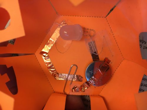
Here are our templates for the top and bottom of the lantern (right-click to save the SVGH files and then open in Inkscape). Red lines are cut or score lines (scoring already drawn as dashed lines) – you can also just print this out on a regular ink printer and cut out the solid red lines with scissors/x-acto knives and fold along score lines.

The blue lines are “vector engraved” on our laser cutter (or again, just printed in a different color on an ink printer) and really just serve as a guide when wiring up the electronics (or where to color in the pumpkin stem on the top). The electronics diagram shows where I suggest placing the LED (and which side is positive) and where I suggest putting the coin battery.

Student workflow:

  1. Put down two strips of copper tape on the solid blue lines
  2. Add the LED (paying attention to which side is positive) and coin battery (positive side facing up) on top of the copper tape and secure those components with Scotch tape
  3. Use the dotted blue line as a guide for the final piece of copper tape, which should go on top of the battery (If your copper tape’s adhesive side is not conductive, then you will need to fold over this copper tape so that the metallic side touches the top of the coin battery and secure THAT down with more Scotch tape)
  4. The little square door on the bottom template will be where you can slide in a paper clip to complete the circuit and turn on the LED.

Photo above shows the completed circuit. The paper clip currently doesn’t complete the circuit, so that’s why the LED is dark. If you move the paper clip to the right a bit, so it bridges the gap between the two copper tape tracks, then circuit will complete and … candle flicker!

Supplies you need:

  • laser cut or printed templates on cardstock
  • Coin cell batteries (I usually buy in bulk from Digi-Key (Product# P189-ND))
  • Copper tape (I usually buy from Sparkfun, but you can also get from Digikey 3M1181A-ND or look for “Slug Tape” at Home Depot/Amazon)
  • Scotch tape
  • Paper clip (acts as a switch in this circuit!)
  • LEDs – we bought 10mm yellow candle flicker LEDs from Evil Mad Scientist because we liked the candle effects
Continue Reading

a twinkling star (and a non-twinkling one too)

Hurray! I finally found time to play with Circuit Stickers!

As much as I love the cuteness of the Circuit Sticker Sketchbook, I’m pretty stingy and wanted to use the stickers for a project in my own notebook instead. So I quickly sketched out a star pattern with pencil, to have as a guide for laying down copper tape. Because I wanted to light 5 LEDs, I needed to wire them in parallel, which is why there are two separate traces on the star. The inner trace is negative and the outer trace is positive.

From there, I wanted to play with the effects stickers, so I watched some of Jie Qi’s tutorial videos. I first tried to add a Twinkle sticker and another LED sticker in the middle of the big star, but space got way too tight. (You can see the random bits of copper tape leftover from experimenting with this configuration in the video.) But since I already had a star, I thought why not add a twinkling star next to it? The wiring here was a bit trickier because I had to cross the positive rail over the negative of the original big star in order to reach the blank part of the page. So I insulated with some Scotch tape to make sure the circuit isn’t shorting. Also because of where the negative and positive terminals of the Twinkle sticker are, I ended up having to run the signal wire past the two terminals under the sticker (again, insulating with some Scotch tape to make sure wires aren’t accidentally crossing).

End result? I love Circuit Stickers! I’m not convinced that they’re scalable for large groups of students – while not super expensive, they do cost more than just buying plain LEDs and batteries (obviously, since they have to be custom-made). But I would buy sets of these as gifts for kids in a heartbeat! Speaking of which, there is a Heartbeat sticker too….!

Continue Reading

a 3D printer assembled!

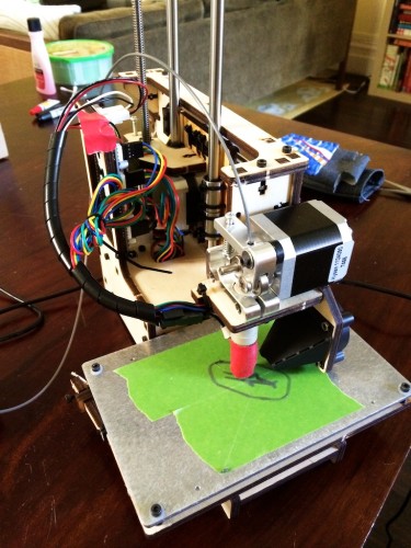
One of the bigger projects I had planned for this summer is to assemble a Printrbot Simple that I had ordered from Amazon at the end of last school year. The kit had been sitting in my house for a few weeks and finally, after all the trips and traveling and conferences were over, I found the time to sit down for a few days, turn on some crappy TV show on Netflix, and tinker with the kit.

I had been thinking of getting a 3D printer for my house for a while now and I specifically wanted to buy one I had to assemble. I thought that if I can build it, I would understand a lot better how they work and this would hopefully be helpful when the one in the lab acts up. Also, during the times when we have a backlog of prints queued up at school, I would be able to help out by doing some prints at home.

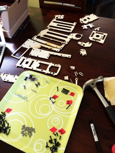
I was a bit intimated when I first opened the kit because there are A LOT of parts, many of which are tiny and can be easily lost. I decided to grab a tray I had lying around and sort all the tiny nuts and bolts on it, which helped the assembly process tremendously.

IMG_1632

Once everything was sorted, I started going through the assembly instructions. I think the only major thing I did was to read through all the comments for each step by other folks before attempting it myself. The comments were really helpful to both clarify the instructions and to warn about tricky parts.

After a few days (working on it a few hours each day), I had an assembled printer!
IMG_1643

The photo above shows the printer already printing but truth be told, it took a few more troubleshooting steps before I could get it to print successfully.

  • I had problems with some of the wires getting caught on the Acme rod when the Z-axis was getting adjusted. To keep the wires out of the way, I used some tape to hold down the wires and get them out of the way as much as possible.
  • I first tested with just the metal bed and prints were just not sticking. We don’t have any blue painter’s tape in the house but we do have Frog Tape from our recent round of painting the stairs. This worked fine.
  • I had to go through the recommended leveling process a few times before I could get the extruder nozzle at an appropriate height. I had first leveled with just the metal bed and forgot to re-level after putting down the painters tape. Even though the tape isn’t all that thick, the difference was enough. I could see the extruder nozzle actually pushing into the tape and carving lines onto it. Re-leveling again fixed it.
  • There were multiple steps after installing Repetier, including using the right settings for the Printbot and updating Slic3r.

The biggest difference I can see from the user angle with Printrbot is that you have to do more things manually. For example, you have to set the extruder temperature and turn it on manually, watch the temperature curve until it reaches the proper temperature, and then start the print. Unlike the Makerbot we have in the lab, all of this isn’t automatically taken care for you. I don’t think this is a deal breaker in terms of putting Printrbots in the lab – it would just require more training before letting kids loose on them.

Continue Reading

a machine sewing class

How do I know it’s truly summer break? Because I just spent a Friday afternoon, during normal work hours, at a Sewing 101 class at Workshop!!

Because the class is during when decent folks are at jobby jobs, there were just me and another teacher as students. Our instructor Aaron was an awesomely hipster young lad who taught himself how to sew and apparently lives with roommates who also sew. It really sounds like every night is a sewing party at their house!

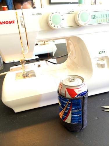
Once Aaron taught us how to set up the machine (I now know what a “bobbin” is), we were off to create our first project – a beer koozie using scrap pieces of fabric.

IMG_1633

He also gave us a short crash course of making simple patterns and how to account for seams. To put this to the test, we each had to make a little pouch for our phones.

Continue Reading

a resource page for paper circuits

One of my absolute favorite making projects is paper circuits. They  are cheap, simple, don’t require any fancy equipment or supplies, and easily adaptable to all sorts of contexts and interests. Once people get the gist of how to make a simple paper circuit, there are many directions they can go: make more complicated circuitry, create interactive stories or posters, incorporate paper circuits into origami or sculptures, etc. The possibilities are nearly endless!

A very basic activity is to make a light-up greeting card or to “bling” out a notebook with a paper circuit on the cover. And Jie Qi, a former(?) grad student at MIT Media Lab’s High Low Tech group, who has done a bunch of work on paper circuits, has recently released a fun Circuit Stickers kit based on the ideas of paper circuitry. While Circuit Stickers are likely not feasible in a classroom setting, they would be fun to buy as toys for kids to play with at home.

Jie also is the one who created the most incredible and lovely interactive painting using paper circuits.

Interactive Light Painting: Pu Gong Ying Tu (Dandelion Painting) from Jie Qi on Vimeo.

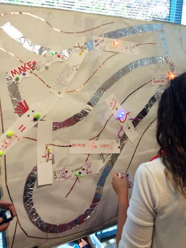
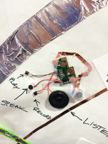
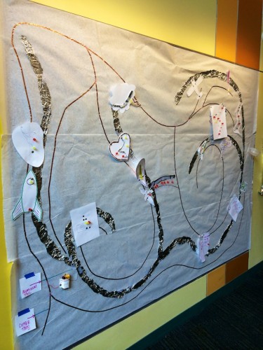
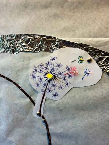
At a conference recently, I saw a fabulous application of paper circuits from the folks at the Exploratory where everyone collaborated on a paper circuit mural. The main difference here is that someone preps a large surface ahead of time with a positive rail and a negative rail (hint: use copper tape for one and aluminum foil for the other to easily tell them apart), hooks them up to battery pack(s) for power, and then gives everyone the materials to create paper circuit pieces to add to the mural. Pieces can be attached using pushpins or magnets, depending on what the backing of the mural is.Exploratory Paper Circuits Exploratory Paper Circuits Recorder

Useful links:

  • Exploratorium’s Tinkering Studio‘s main project page for paper circuits has great examples, suggestions on where to buy supplies, and a PDF activity guide.
  • The Tinkering Studio wrote a blog entry on paper circuits that has great tips on facilitation strategies and common challenges.
  • High-Low Tech group’s site has an online tutorial and a one page handout with templates and materials list, including part numbers for Digikey, which is a cheap vendor for electronics materials.
  • The fabulous Lindsey Own, who ran a workshop session on alternative circuits with Jenny Howland at the professional development event we ran back in June, has a nice blog entry with tips and tricks for working with paper circuits.

Tips & tricks:

  • Any 3V coin cell batteries will work. I usually buy CR2032 because I can use them for other things too and I like that they’re pretty flat.
  • For the most part, I use regular two-legged LEDs but I have since learned about using surface mount LEDs for tiny lights that lay flatter on the page or LEDs with axial leads for easier wiring.
  • Copper tape can be bought from hardware stores as snail tape or EMI shielding tape from electronics stores. Tinkering Studio has some tips on which brands are best.
  • Instead of taping down the leg of an LED onto the paper, first lay down a piece of copper tape. Put the leg on top and then tape that down with another smaller piece of copper tape. This will ensure that the metallic leg of the LED has good contact with the shiny, more-conductive side of the copper tape.
  • As much as possible, avoid creating circuit paths with multiple pieces of tape and instead, turn corners with one piece of tape. This will ensure good current flow.

Stuff to buy:

Continue Reading

a paper circuit mural

Yup, I’m pretty much obsessed with paper circuits lately, so here they are making yet another appearance!

For the past two days, I’ve been over at Lighthouse Community Charter School’s Creativity Lab helping out with some professional development workshops they’re running. When Aaron and I were brainstorming how to structure the day, one of the things he really wanted was to kick off the morning with some active making. I mentioned that at the Making Possibilities workshop a while back, I saw a really cool adaption of paper circuits where everyone collaborated on a mural. When he presented this to his team back at LCCS, they liked the idea and immediately work on making the mural base for it.

After breakfast on day 1, we asked participants to create pieces to add to the mural. The activity became both an ice-breaker and the mural itself became like a “water fountain” as people gathered around to chat about electricity or what not. The funniest moments were when someone accidentally shorted the mural, turning everyone’s lights off, and the whole group would all gasp!

IMG_1599

And here’s my little contribution to the mural. I know I know, I wasn’t feeling super crafty that morning so I just turned to an old favorite. 😉

IMG_1597

Continue Reading

a workshop on paper circuits

Funny thing: one of my good friends’ sister is apparently the Director of Education over at the Contemporary Jewish Museum and I never even knew it! To be fair, she also didn’t know what I do because every time we see each other at parties, we would just talk about food and cooking – another shared interest of ours. 🙂

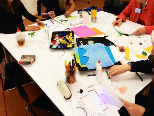
So when she found out what I do for a living, she graciously invited me to host a session on making in education at the Jewish Educational Technology Institute. And as a bunch of us maker lab directors like to say, one should never just tell people about making but make sure they experience it for themselves. To keep things simple, fun, and crafty, I decided to do a workshop on paper circuits especially since the attendees were mostly humanities teachers and I think paper circuits have great potential to integrate into the humanities.

The crew at CJM was so awesome and ordered all the supplies we needed the week before (while I was away at CMK 2014). They also dug up a whole bunch of craft materials from their stock room to ensure maximum making fun!

IMG_1589

For the first timers, I suggested that they start with the simple circuit template from Jie Qi’s Circuit Stickers Sketchbook. From there, they could try making a circuit with a switch or even more complex circuits.

IMG_1590


Continue Reading

an interactive neuron

At CMK 2014, after I had just about run out of ideas of what else i can do with fabric speakers, I found out that my friend Aaron and his group were working on another e-textiles project and trying to figure out how to use Arduino to control a bunch of NeoPixels and lights. And they graciously allowed me to crash the party.

Their project idea was awesome – build an interactive representation of a neuron that will sense when someone is near by and “fire” action potentials accordingly. They had already done a lot of the soldering and sewing work, so it was time to jump into the Arduino coding – yay, my favorite! One tricky part of this project was that they couldn’t find enough NeoPixels to cover the whole neuron, so ended up using a combination of NeoPixels and regular LEDs. Each regular LED was connected to a PWM output pin of the Arduino (so that we can control brightness). All the NeoPixels were wired in series and connected to a single Arduino pin – I do love that you only need one pin to control a whole bunch of NeoPixels!

After much initial head-scratching and whining about the difficult of working with the NeoPixels Arduino library and the not-exactly-intuitive documentation, we finally pulled together code that works! When the ultrasonic sensor does not sense anyone (or any object really) nearby, the lights all along the neuron will twinkle and randomly fade on/off. When the sensor senses someone close by, it will trigger a “firing” pattern, starting from the axon terminal, propagating up the axon, and spreading through to the dendrites. If the person/object isn’t close enough, the firing pattern only goes partway up the axon. You can see all three cases in the video above.

And because we love sharing, here’s our Arduino code:

#include <Adafruit_NeoPixel.h>

#define PIN 6
#define NUMPIXELS 25
#define NUMNEO 20
#define ARRAYSIZE 10

#define echoPin 7 // Echo Pin
#define trigPin 8 // Trigger Pin


// records whether a pixel is currently on or off... 
// first batch is neopixels and then normal LEDs
int state[NUMPIXELS]; 

int LEDpins[5] = { 
  3, 5, 9, 10, 11}; // pin numbers for the non-neopixel LEDs

// during explosion sequence, this is the order the lights should light up in
int sequence[NUMPIXELS] = {
  0,1,2,3,20,21,22,23,24,4,5,6,7,8,9,10,11,12,13,14,15,16,17,18,19};
int vel=100;

// array to hold light sensor readings so we can keep an average
int sensorReadings[10];
long counter = 0;

// for ultrasonic sensor 
int maximumRange = 150; // Maximum range needed
int minimumRange = 0; // Minimum range needed
long duration, distance; // Duration used to calculate distance


// create neopixel strip object
Adafruit_NeoPixel strip = Adafruit_NeoPixel(NUMNEO, PIN, NEO_GRB + NEO_KHZ800);

void setup() {

  // set up the averaging array 
  counter = 0;
  for (int i=0; i< ARRAYSIZE; i++)  {
    sensorReadings[i] = 0;
  }

  strip.begin();
  clear_all();

  // set up ultrasonic pins
  pinMode(trigPin, OUTPUT);
  pinMode(echoPin, INPUT);

  Serial.begin(9600);
}


void loop() {

  // send pulses with ultrasonic sensor to detect distance
  digitalWrite(trigPin, LOW); 
  delayMicroseconds(2); 

  digitalWrite(trigPin, HIGH);
  delayMicroseconds(10); 

  digitalWrite(trigPin, LOW);
  duration = pulseIn(echoPin, HIGH);

  //Calculate the distance (in cm) based on the speed of sound.
  distance = duration/58.2;
  if (distance >= maximumRange || distance <= minimumRange){
   // Serial.println("out of range == TWINKLE!!");
    twinkle();
    counter = 0;
  }
  else {
    int thisIndex =  (counter % ARRAYSIZE);
    sensorReadings[thisIndex] = distance;
    counter++;

    // now calculate the average distance object is at
    int sum = 0;
    for (int i=0; i<ARRAYSIZE; i++) {
      sum += sensorReadings[i];
    }
    float average = sum/ARRAYSIZE*1.0;
      
    if (counter > 10) { // don't do anything until we've read 10 readings
     // convert average distance to number of LEDs to light
     float y = -1.0/12*distance + 32.0/3.0;
     clear_all();
     
     if (y >= 9.0) {
      explosion(24);
     } else {
       explosion((int) y);
     }
    }
  }
}


void explosion(int stop_point){
  strip.setBrightness(120);
  for (int i = 0; i<stop_point; i++){
    int lightIndex = sequence[i];
    if(lightIndex < NUMNEO){
      if(lightIndex < 4){
        strip.setPixelColor(lightIndex,255,255,255);
      }
      else{
        int r = random(255);
        int g = random(255);
        int b = random(255);
        strip.setPixelColor(lightIndex,r,g,b);
      }
      strip.show();
      delay(vel);
    }
    else {
      digitalWrite(LEDpins[lightIndex-NUMNEO], HIGH); 
      delay(vel);
    }
  }
  delay(1000);

  for (int i = stop_point; i>=0; i--){
    int lightIndex = sequence[i];
    if(lightIndex < NUMNEO){
      strip.setPixelColor(lightIndex,0,0,0);
      strip.show();
      delay(vel);
    }
    else {
      digitalWrite(LEDpins[lightIndex-NUMNEO], LOW); 
      delay(vel);
    }
  }
}

// random twinkling effect
void twinkle(){
  int pickMe = random(NUMPIXELS);
  strip.setBrightness(200); 

  if(state[pickMe]==1) { //fadeout
    fade_down(pickMe);
    state[pickMe] = 0;

  }
  else { //fadein
    fade_up(pickMe);
    state[pickMe] = 1;
  }
}

// fade the lights in
void fade_up(uint16_t u) {
  // pick a random color for the neo-pixels
  int r = random(255);
  int g = random(255);
  int b = random(255);

  for (int k=0; k<= 100; k++) { 
    if (u < NUMNEO) {
      strip.setPixelColor(u,k*r/100,k*g/100,k*b/100);
      strip.show();
      delay(5);
    } 
    else{
      analogWrite(LEDpins[u-NUMNEO], k*50/100);  
      delay(5);  
    }
  }
}

// fade the lights out
void fade_down(uint16_t u) {
  // figure out what color a neopixel is, if it's a neopixel
  uint8_t r,g,b;
  if (u< NUMNEO) {
    uint32_t c = strip.getPixelColor(u);
    r = (uint8_t)(c >> 16),
    g = (uint8_t)(c >>  8),
    b = (uint8_t)c;
  }
  for (int k=100; k>= 0; k--){ 
    if (u < NUMNEO) {
      strip.setPixelColor(u,k*r/100,k*g/100,k*b/100);
      strip.show();
      delay(5);
    } 
    else {
      analogWrite(LEDpins[u-NUMNEO], k*50/100);  
      delay(5);  
    } 
  }
}

// turn off all the lights, neo-pixels and normal LEDs
void clear_all() {
  for(int i=0; i<NUMPIXELS; i++){ //initialize strip off
    state[i]=0;
    if (i >= NUMNEO) {
      pinMode(LEDpins[i-NUMNEO], OUTPUT);
      digitalWrite(LEDpins[i-NUMNEO], LOW);

    } 
    else{ 
      strip.setPixelColor(i,0,0,0); 
    }
  }
  strip.show(); 
}
Continue Reading

a fabric speaker

Amongst the plethora of ideas at CMK 2014, one that stuck with me was the idea of wearable speakers, as I’ve been wanting for some time now to delve deeper into soft circuits and e-textiles. Specifically, I wanted to challenge myself to build actual speakers using simple materials instead of just embedding pre-made speakers into a wearable device. Although I didn’t have anyone to work with on this specific project, I ended up getting situated at a table of other folks working on individual projects, which gave me the best of both worlds: people to chat with/bounce ideas off of, yet total creative freedom in how I want to approach the project. (Which incidentally, is giving me ideas about the benefits of allowing students to opt to work by themselves on some projects.)

The first thing I did was to consult the interwebs to see if others had done similar projects and as is usually the case, someone also had this idea.  I first found this Instructables which gave me a great overview and also led me to this page with even more ideas and examples. Although I’ve taught electromagnetism in my engineering classes before, it still never fails to delight me when I get to build something using magnets and wire that will actually work!

With some research under my belt, I was ready to start prototyping. Although I didn’t have access to the exact types of conductive threads my references used, there were conductive yarn and the other types of conductive threads at the conference, so I decided to play with those. A quick measurement with the multimeter told me that the yarn had much higher resistance, so I opted to work with the conductive thread instead.

IMG_1547

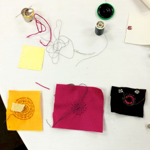
My first prototype is the orange one of the left, where I sewed conductive thread into a spiral onto a small piece of felt. When I place it over a super strong magnet (courtesy of Jaymes) and put my ear really close to it, I can just make out the sound.  But given how large the magnet had to be (you can see it at the top of the photo and how literally anything sort of magnetic just get stuck to it Katamari-style), it didn’t exactly seem reasonable for wearable applications.

For my second iteration (magenta one in the middle), I used the same general idea but patiently tried to sew a tighter spiral to see if that would increase the output enough to be audible with just a small disc magnet or two – no luck. Upon further research, I realized that the example fabric speakers I saw all went through a simple amplifier circuit, for which I don’t have the parts. That meant conductive thread might be a dead end until I get home when I can order the chip I need to build an amplifier circuit.

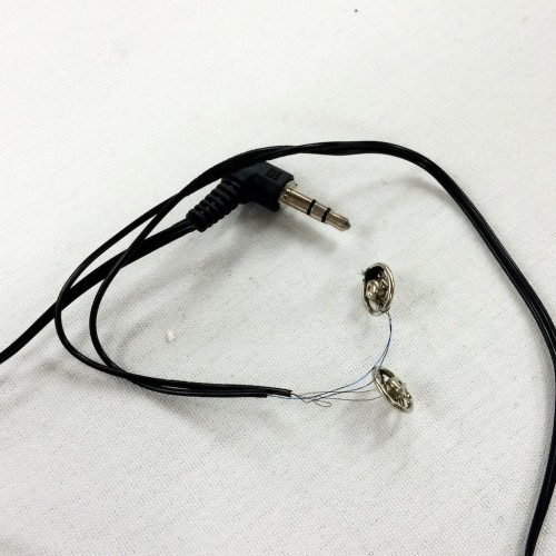
So for my third iteration (black version on the right), I decided to forego the conductive thread altogether and just use normal magnet wire because it has an insulating coating which allows you to coil the wire over itself many many times over, thus creating a much stronger magnetic field. (Sadly, you can’t do that to conductive thread because the whole surface of the thread is conductive.) At this point, I had also gotten tired of my testing protocol of twisting very fine wires together, so I decided to sew snaps onto my speaker (you can see them on the photo above) and solder the other sides to my deconstructed earphones to make a better testing platform. I had to take a pair of cheapo airplane headphones apart in order to get a jack to connect to my computer/iPhone.

IMG_1548

This iteration actually worked ok when paired with two little disc magnets that I duct-taped onto a stretchy piece of fabric, especially when you add a stiff piece of paper onto the whole thing as a membrane that will push the air more effectively. It’s nothing that will rock your socks off but if you hold the whole thing up to your ear or if you are in a quiet room (which is hard to find at CMK), you can actually hear the music! 🙂 And actually, if you hook this up to an amplifier (which again, Jaymes had), it will be quite booming…at least until the wire gets so hot that it melts the felt and the whole thing starts smoking! Exciting!

IMG_1552

In the photo above, you can see that I added a small resistor to the coil just to make sure the speaker will have about 10Ω of resistance – supposedly, if speakers have lower resistance than 8Ω (which is what normal pre-made speakers are), it can mess up your audio source. I don’t know if this is absolutely true but I certainly wasn’t about to risk my computer or phone to test this out!

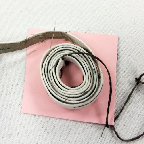
One idea that came to me while I was working on this last version was if there’s a way to coil up conductive materials like the wire to create a bigger magnetic field, so I tried to make a version where I sandwiched a long strip of conductive fabric in between non-conductive fabric and rolled the whole thing up. Cool idea, right? TOTAL FAIL! Ah well, it was worth a try!IMG_1551


Continue Reading